
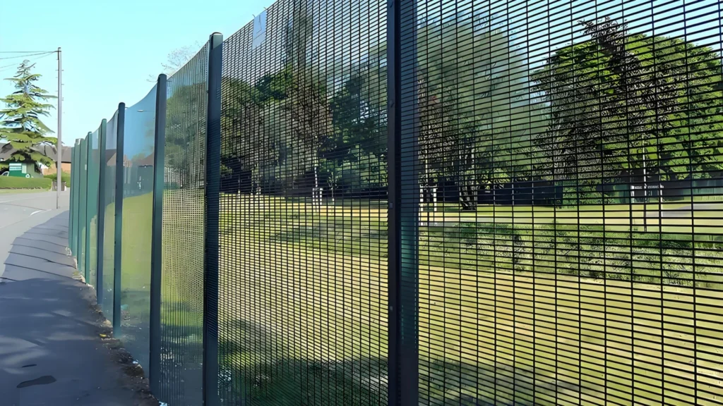
Estudio de caso de perímetro industrial | malla soldada, hilos, alambre de afeitar y pie aislado
Una valla de alta seguridad alrededor de una instalación petroquímica u otra industrial es más que un panel de malla y un poste. El cálculo suministrado por Fujian petrochemical-facility considera la malla soldada, brazos de extensión en forma de Y, bobinas de afeitar espiral, hardware de conexión, postes de acero y fundaciones de hormigón aislado. Las acciones eólicas en estos componentes siguen una ruta de carga a través de las conexiones y puestos a las fundaciones y el suelo de apoyo.
Este artículo resume el informe de cálculo de código chino suministrado. Sus resultados numéricos están vinculados a la geometría de ese informe, las suposiciones materiales, los parámetros del viento y las suposiciones fundamentales. No deben tratarse como un certificado de diseño para otro sitio o como sustituto de los cálculos bajo los códigos de una jurisdicción diferente.
1. Definir el sistema de cerca y la unidad de cálculo
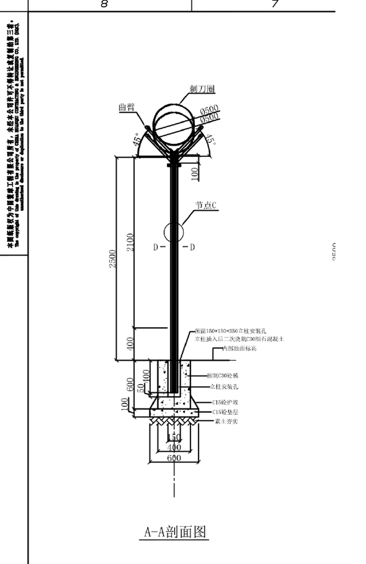
El informe comprueba una unidad de carga estándar: un espaciamiento de 2,550 mm, un post intermedio, medio panel de malla en cada lado, las bobinas superiores Y-arm y alambre de cuchilla, y un pie de hormigón aislado.
| Componente | Configuración informada |
|---|---|
| Puesto | 62 × 95 × 1.2 mm sección de paredes delgadas multicelular de forma fría; las propiedades de grado Q235 asumidas |
| Espaciamiento de puestos estándar | 2.550 mm; espaciamiento de extremo y esquina reportado como 2,525 mm |
| Altura de postes sobre tierra | 2.500 mm |
| Malla soldada | alambre vertical Ø5 mm a 50 mm; alambre horizontal Ø6 mm a 200 mm |
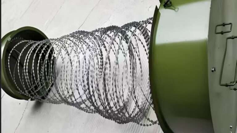
| Montaje de seguridad superior | 45° Y-arma con dos espirales de afeitado en espiral Ø500 mm |
| Footing | C30 hormigón, 600 × 600 mm; C15 capa de cegado 100 mm de espesor |
| Post embedment | 400 mm, fijado por fundición secundaria con hormigón fino C30 |
|
2. Establecer la base eólica y la exposición de componentes
Para el proyecto costero Fujian, el informe adopta una presión básica del viento w0 = 0,80 kN/m2, correspondiente a una velocidad de viento básica de 35,8 m/s. Utiliza la categoría B del terreno y un coeficiente de altura μz = 0.660 en z = 2,5 m. El informe trata al viento como la acción gobernante para este sistema de vallas de bajo peso ligero.
El informe distingue la estructura principal de postes de componentes y conexiones de revestimiento: βz = 1.0 para la estructura principal, y factor de encía βgz = 1.70 para la malla soldada, clips, y-armas, bobinas de afeitar y sus conexiones. Estos son los valores y el método indicados en el informe fuente; un ingeniero de proyectos debe confirmar los coeficientes correctos para el sitio real y el código de gobierno.
El informe de origen utiliza diferentes supuestos de solidez para diferentes partes: la malla soldada tiene una relación de solidez calculada φ = 0,13 y coeficiente de forma μs = 0,169; la bobina de alambre de afeitar se asigna una relación de solidez equivalente de 0,15 y μs = 0,195; el post en sí utiliza un ancho de viento de 0,062 m y μs = 1.3.
|
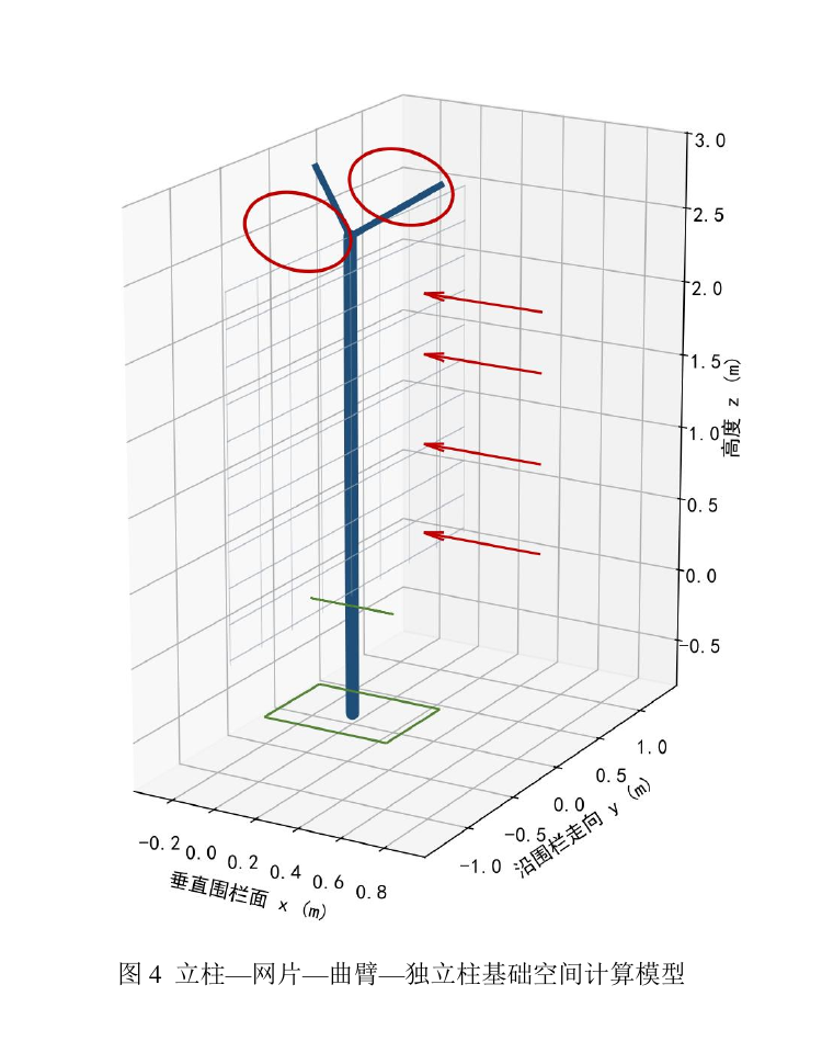
3. Calcular la carga transferida al puesto
Para el lapso estándar de 2,55 m, el informe calcula las siguientes características de las fuerzas eólicas y las contribuciones de base. Las alturas de los componentes difieren, por lo que sus contribuciones de momento individuales deben ser consideradas.
| Componente cargado | Coeficiente de forma μs | Fuerza de carácter | Altura de carga | Momento de base |
|---|---|---|---|---|
| malla soldada (+0,4 a +2,5 m) | 0.169 | 0.471 kN | 1,53 m | 0,722 kN·m |
| Bobinas Razor-wire (+2,5 a +2,85 m) | 0.195 | 0.109 kN | 2.68 m | 0.292 kN·m |
| Post (0 a +2,85 m) | 1.30 | 0,008 kN | 1,73 m | 0,014 kN·m |
| Total | — | 0,58 kN | — | 1.016 kN·m |
Utilizando el factor de carga eólica del informe de 1.5, el revestimiento de diseño es Vd = 0.882 kN y el momento de curvado de diseño es Md = 1.524 kN·m. Simplemente multiplicar la fuerza total por el espaciamiento post perdería las diferentes alturas de carga y sus efectos en el momento base.
4. Repaso de la fuerza post y la deflexión lateral
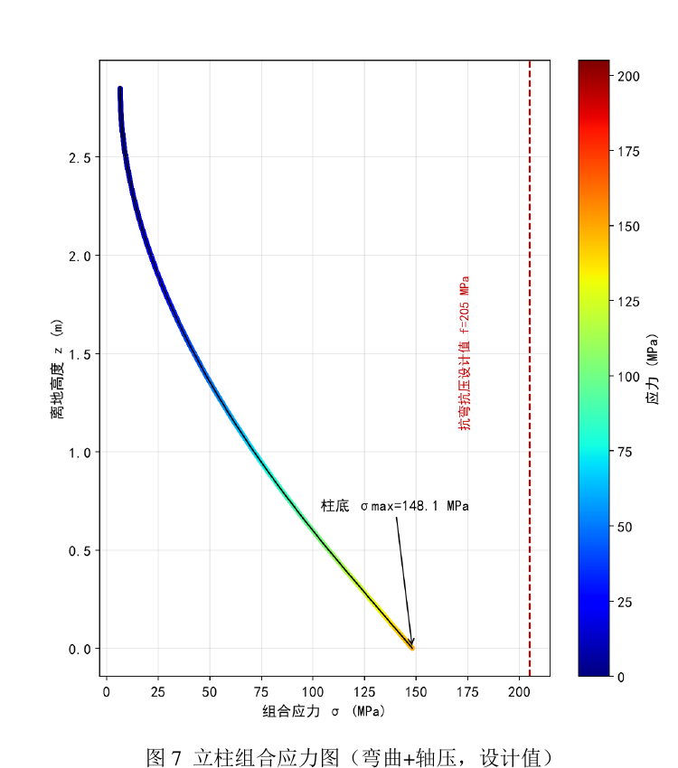
The report models the post as a cantilever fixed at its base and free at the top. It gives a gross section area A = 518.3 mm², strong-axis second moment of area Iv = 511,493 mm⁴ and strong-axis section modulus Wv = 10,768 mm³.
| Check | Reported result | Reported criterion |
|---|---|---|
| Combined bending and axial stress | 148.1 MPa | ≤ 205 MPa; stress ratio 0.723 |
| Shear stress | 3.1 MPa | ≤ 120 MPa |
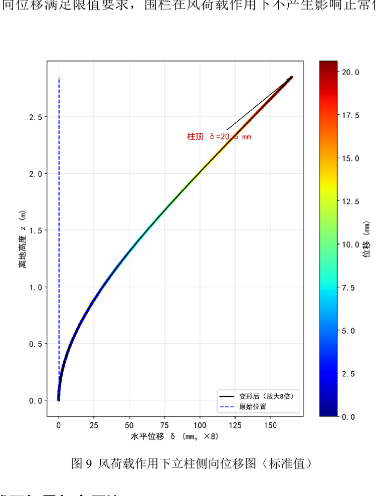
| Top lateral displacement | 20.63 mm | ≤ H/60 = 41.7 mm |
| Section plate width-to-thickness ratio | b/t ≈ 20 | Report treats gross section as effective |
The report concludes that the post meets its stated strength and displacement checks. These conclusions depend on the stated Q235-grade material assumption, section geometry, load model and boundary conditions. If the supplied post’s grade, thickness or section shape differs, the calculation must be reviewed.
|
|
5. Check connections separately
The report applies βgz = 1.70 to the mesh and connection components. It reports a factored mesh force of about 1.20 kN per span; with roughly seven clips per side, the estimated design horizontal force per clip is about 0.086 kN. For the top razor-wire assembly, it reports a gust-adjusted characteristic force of about 0.185 kN and a design force of about 0.28 kN transferred through the Y-arm and clamp.
The report judges the described clips, bolts and clamps adequate under these assumptions. For a real project, confirm the actual connector material, size, quantity, spacing, edge distances and installation method. A generic description cannot replace checking the actual connection detail.
6. Verify the footing and ground assumptions
The report uses a C30 isolated footing measuring 600 × 600 mm in plan and 600 mm high, with a 100 mm C15 blinding layer. The footing base is reported at 0.75 m depth, and the post is embedded 400 mm into a reserved opening and fixed with secondary C30 fine-aggregate concrete.
| Foundation check | Reported result | Report criterion |
|---|---|---|
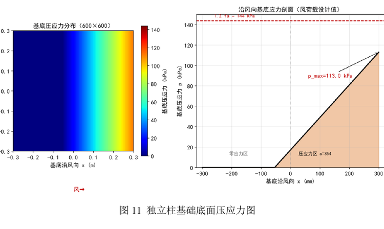
| Maximum soil bearing pressure | 113.0 kPa | ≤ 144 kPa |
| Overturning stability factor | 1.65 | ≥ 1.5 |
| Sliding stability factor | 8.55 | ≥ 1.3 |
A key qualification in the source is that the soil bearing-capacity value fa = 120 kPa is provisional. The report says it must be replaced by the value in the formal geotechnical investigation report. If actual ground conditions are weaker, footing size, embedment or ground improvement may need to be revised by the project designer.
|
Conclusion: Design the full load path
High-security fence wind-load design should follow the load path from the mesh and top security assembly through the connections and posts into the footing and soil. For this Fujian case, the report gives a maximum combined post stress of 148.1 MPa, top displacement of 20.63 mm, maximum foundation bearing pressure of 113.0 kPa, overturning factor 1.65 and sliding factor 8.55. Those results apply only to the report’s inputs, assumptions and stated checks.
About Commandfence
Commandfence supplies metal fencing and perimeter-security products for industrial and infrastructure applications. Share your drawings, project location, fence height, wind criteria and foundation constraints to discuss a configuration aligned with the project specification.
For projects comparing alternative anti-climb mesh configurations, review Commandfence’s 358 fence range. The linked product family should be assessed against the project specification rather than assumed to be equivalent to the configuration calculated here.
Send Commandfence your drawings, required fence height, site wind criteria and foundation constraints for a project-specific product discussion. To start a project discussion, send your drawings and site criteria through Commandfence’s quote form.
Engineering Disclaimer
Before applying this information to an actual project, qualified structural engineers must verify the project loads, materials, fence components, connections, foundations, geotechnical conditions, and compliance with the codes and regulations applicable at the project location. The source report also identifies the soil bearing-capacity value as provisional and requires confirmation against the formal geotechnical investigation report. Do not use this article as the sole basis for engineering approval, construction, or procurement decisions.
This article is provided for general information and reference purposes only. It is not a certified structural design, project-specific engineering approval, or guarantee of performance. The calculations are based on Chinese engineering codes and standards and should not be assumed to demonstrate compliance with the codes or regulations of other countries or jurisdictions.
The calculations and technical information presented in this article are based on the project-specific assumptions, calculation methods, and Chinese engineering codes and standards identified in the source report, including the applicable Chinese national and Fujian provincial standards cited therein. The reported results apply only to the stated project configuration, design inputs, calculation assumptions, and site conditions.





Responder