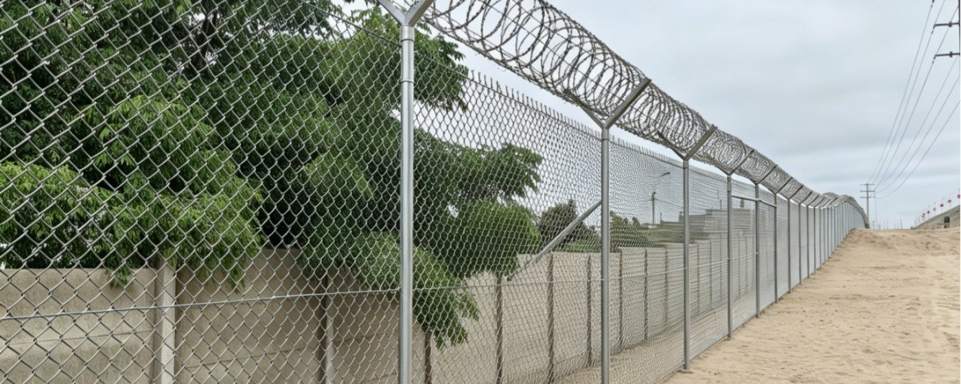
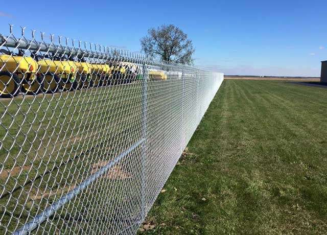
A professional chain link fencing solution designed for durability, corrosion resistance, and reliable perimeter protection. The system includes chain link mesh, posts, struts, line wires, clamps, extension arms, barbed wire, and optional concertina razor wire.
Fencing Overview
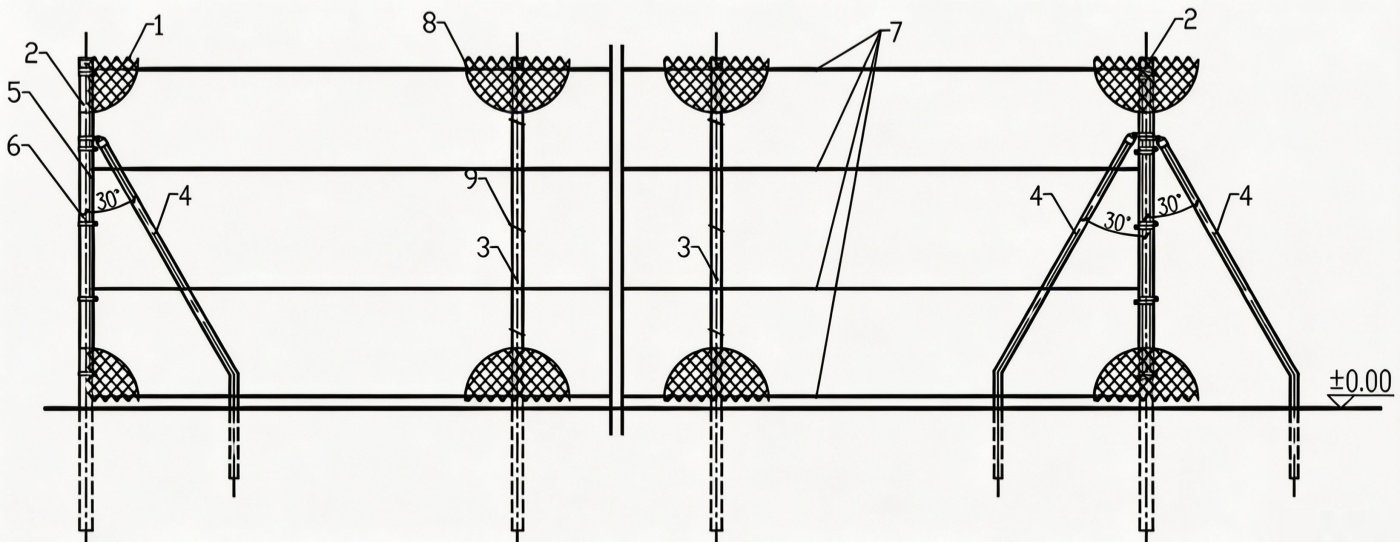
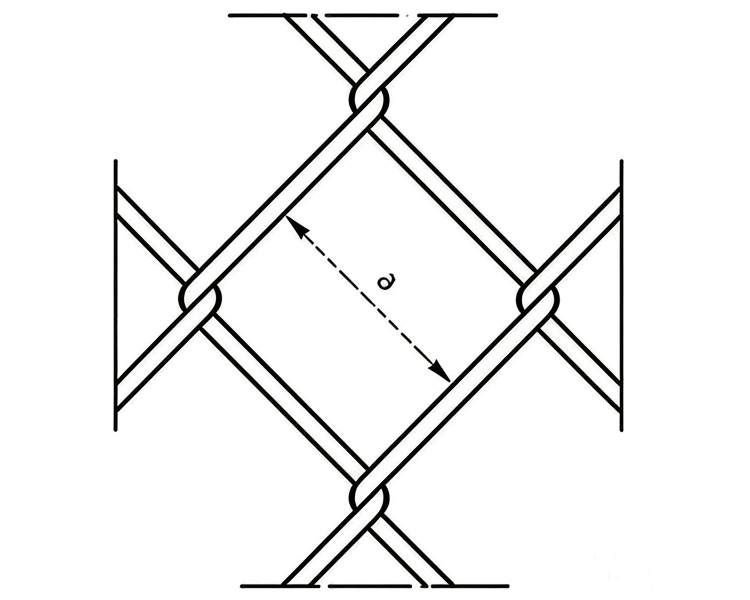
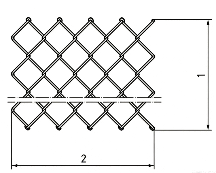
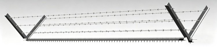
Chain Link Fence Elevation Drawing
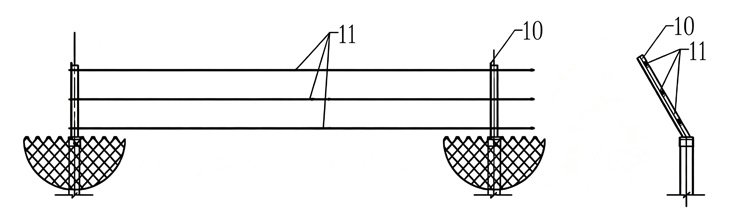
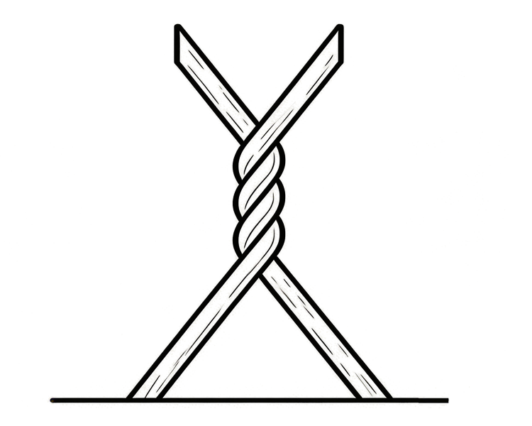
Connection Assembly
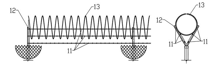
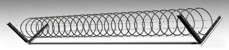
Top Security Detail
1
Chain Link
2
Straining Post
3
Intermediate Posts
4
Strut
5
Stretcher Bar
6
Band Clamp
7
Line Wire
8
Stainless Steel Mesh Clip
9
Wire Ties
10
Steel Flat Extension Arm
11
Barbed Wire
12
Steel Flat Extension Arm
13
Concertina Razor Wire
Compliance with
Standard
Specification
BS 1722-1:2019
Part 1: Specification for Chain Link Fences
BS 1722-10:2019
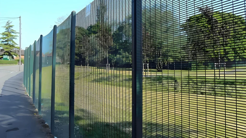
Part 10: Specification for Anti-Intruder Fences in Chain Link and Welded Mesh
BS 1722-16:2009
Part 16: Specification for Powder Coatings Used as a Plastics Finish to Components and Mesh
BS EN 10223-6:2012
Steel Wire and Wire Products for Fencing and Netting – Part 6: Steel Wire Chain Link Fencing
BS EN 10244-2
Steel Wire and Wire Products – Non-Ferrous Metallic Coatings on Steel Wire – Part 2: Zinc or Zinc Alloy Coatings
BS EN ISO 1461
Hot-Dip Galvanized Coatings on Fabricated Iron and Steel Articles – Specifications and Test Methods
BS EN ISO 12944
Paints and Varnishes – Corrosion Protection of Steel Structures by Protective Paint Systems (Parts 1–8)
Chain link panel
This document (EN 10223-6:2012) has been prepared by Technical Committee ECISS/TC 106 “Wire rod and wires”, the secretariat of which is held by AFNOR.
This European Standard shall be given the status of a national standard, either by publication of an identical text or by endorsement, at the latest by May 2013, and conflicting national standards shall be withdrawn at the latest by May 2013.