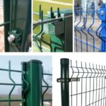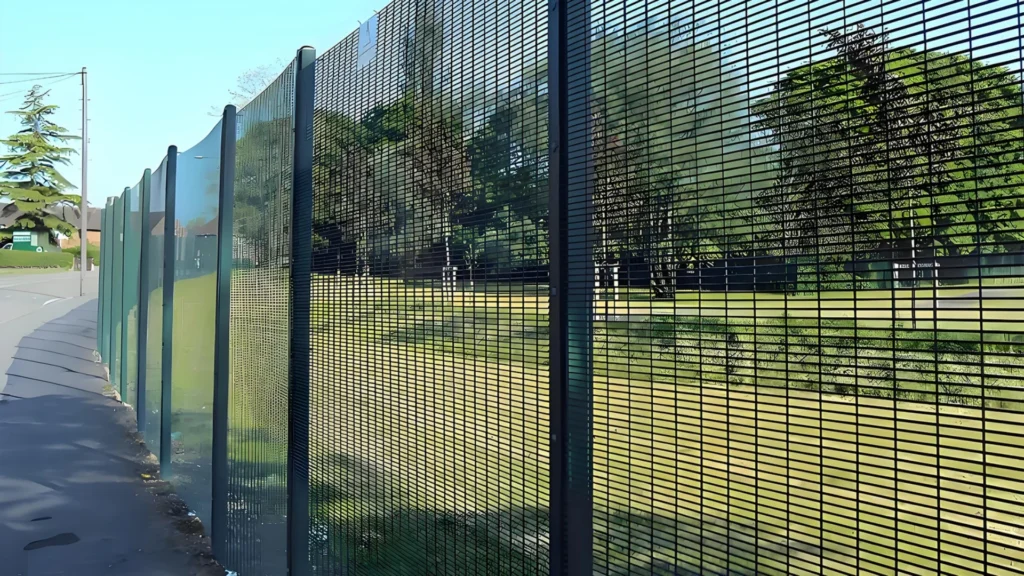
When fence installation encounters problems, the first visible symptom may be an overlong panel, incompatible post-hole positions or a gate leaf touching the ground. The underlying problem, however, may already be present in the procurement drawings: inconsistent dimension definitions, missing levels or different drawings using different revisions.
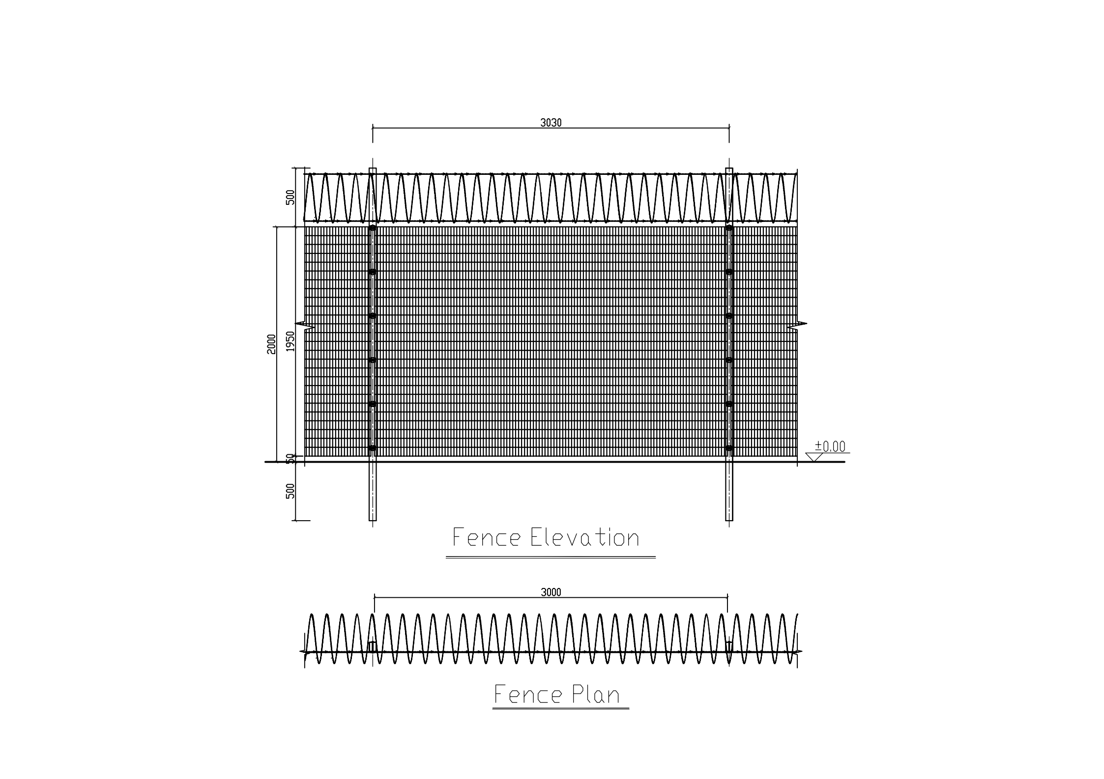
An installation-focused drawing review before issuing the production schedule can turn many of these issues into details that can be confirmed. This article explains checks at common interfaces. The supplied drawing supports the review discussion and is not presented as a record of a customer rework case.
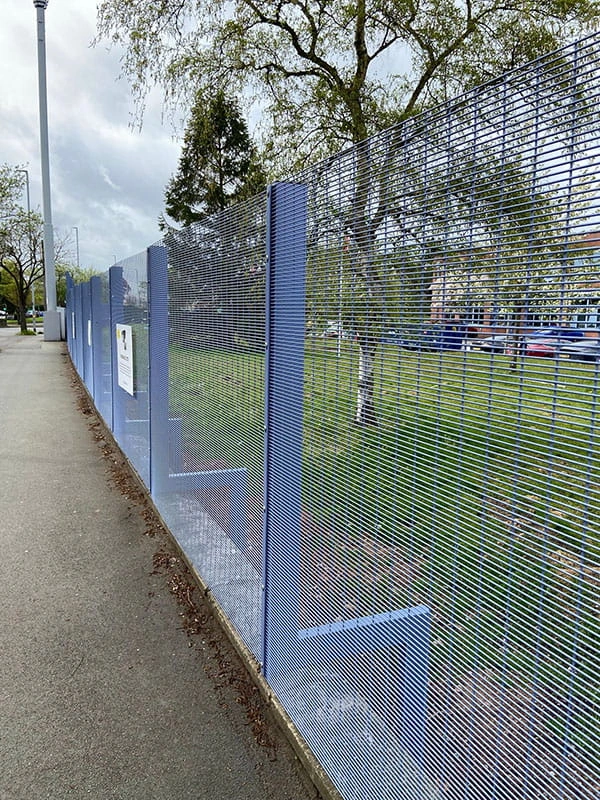
The site plan and details use different revisions
A site plan may show a revised gate opening or fence alignment while the material schedule still uses the old quantities. Similar information gaps can occur between gate schedules, elevations and foundation drawings.
State the drawing number, revision and applicable scope in the production approval documents. A change requires more than a revised image: check the affected panel quantities, post positions, accessories and packing identification. Verbal agreement in a chat record is not enough.
Panel width is copied directly into post centre spacing
Panel width, post centre spacing, clear distance between posts and connection overlap are related dimensions. One correct value does not mean the same number can simply be copied into every other dimension.
Select a standard bay and show the panel, posts on both sides and fixings together in one detail. Then check end bays, connections to gate posts and corners to confirm that the setting-out dimensions match the actual product construction.
Plan lengths are provided without finished ground levels
A plan shows where the fence runs, but does not by itself establish the exposed fence height or bottom clearance on sloping ground. Later paving, kerbs and changes in retaining-wall height can affect posts and gate leaves that have already been ordered.
Provide an elevation or key levels along the slope, distinguishing existing ground from the final finished surface. Coordinate panel steps, post-top levels and foundation-top levels so that site cutting or improvised packing does not become the default solution.
Corners fit on the drawing but leave no tool access
Where two panels change direction at one post, clamps may interfere with one another and bolts may be impossible to insert from the intended side. Connections next to walls or equipment need particular attention to working space.
For non-standard corners, state the angle and measurement reference and provide an enlarged plan detail. If a standard connection cannot be used, agree on dedicated brackets, separate posts or special panels before delivery rather than modifying holes arbitrarily on site.
Gate and foundation interfaces are left until last
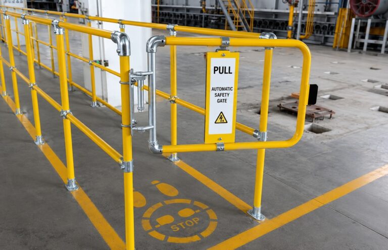
A gate-opening dimension may mean clear passage width or a post-centre control dimension. Swing gates also require checks on ground levels throughout their opening area, while sliding gates need their run-back space and operating conditions checked. For a cantilever sliding gate, use the approved gate arrangement to coordinate the opening, supports and run-back area.
Foundation drawings should correspond to actual post positions, base-plate hole spacing and the completed civil works level. Unclear buried services, wall-top installation conditions or anchorage requirements should be listed as specific items for confirmation before production. A generic foundation detail cannot resolve every interface.
Turn drawing-review questions into a CommandFence confirmation schedule
Identify standard bays, slopes, corners, gate areas and foundation interfaces separately when reviewing drawings and material schedules with CommandFence. This helps prevent the same issue from recurring in different documents. The approved revision should provide the common basis for production and acceptance.
Provide the site plan, key elevations and site photographs together. CommandFence can coordinate the fencing system and related components around the drawings and specifications, helping dimensional questions receive proper attention before materials leave the factory.
For panel systems such as 2DG double-wire mesh fencing, confirm the panel-to-post arrangement against the selected product detail before approving setting-out dimensions.
Explore CommandFence fencing products and project configuration options.