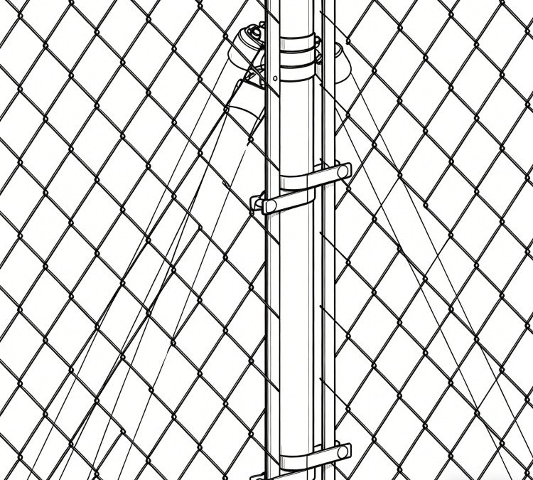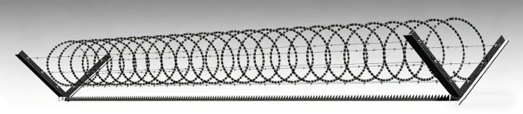
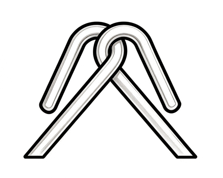
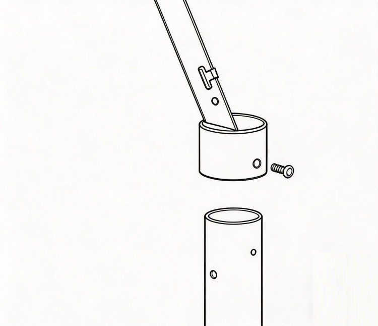
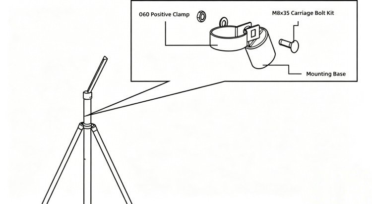
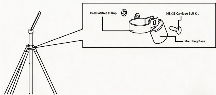
Connection Assembly
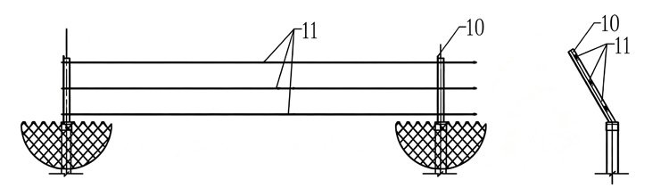
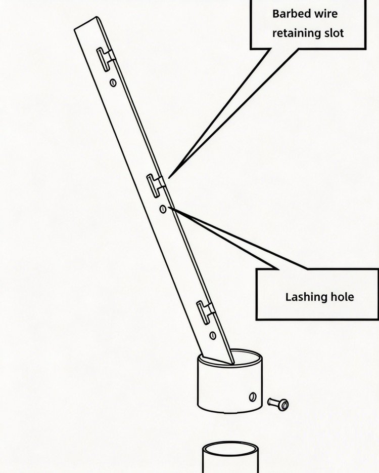
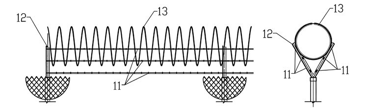
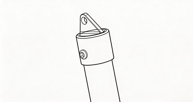
Top Security Detail
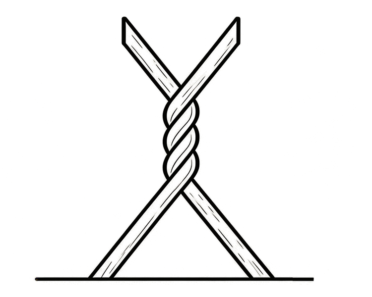
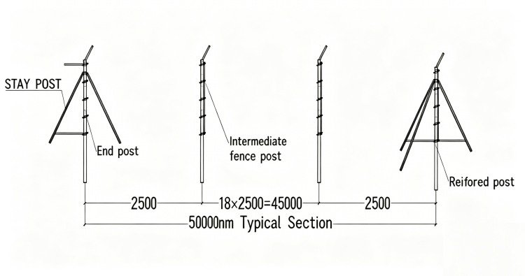
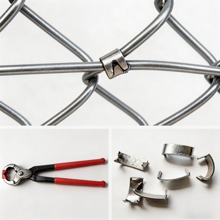
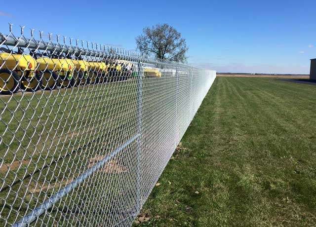
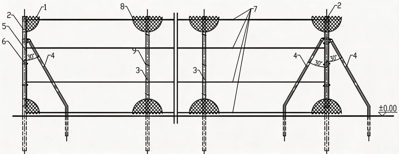
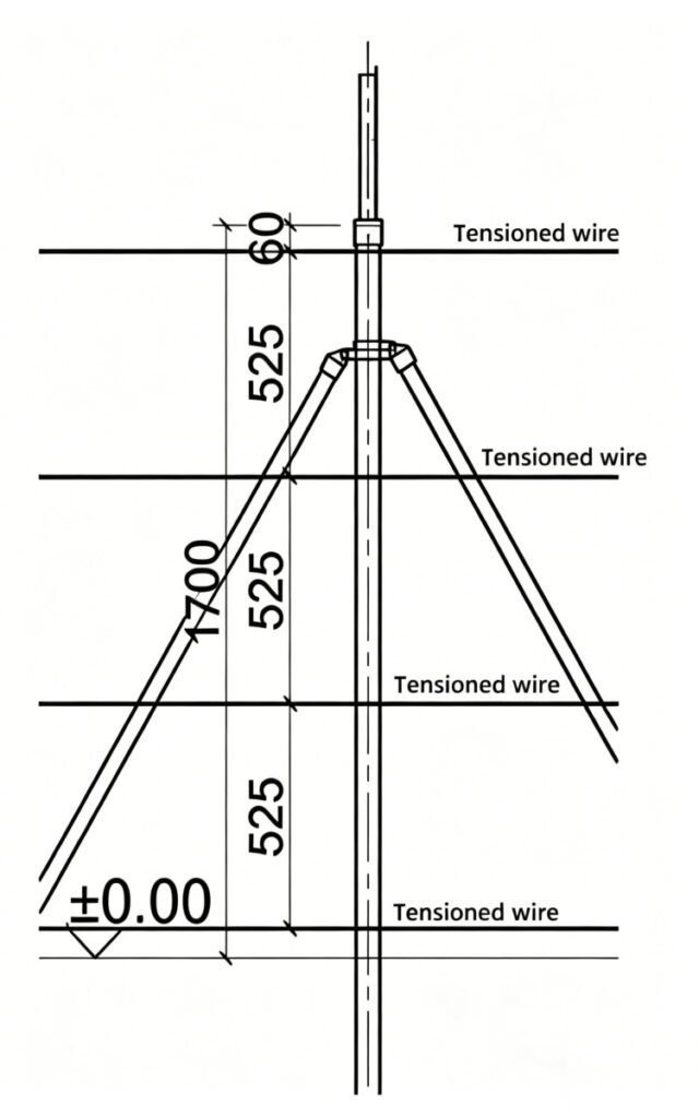
Step 6: Install the tension wire
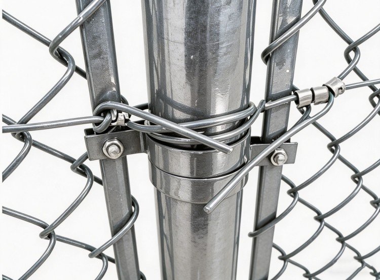 Secure the tension wire to end and reinforced posts.
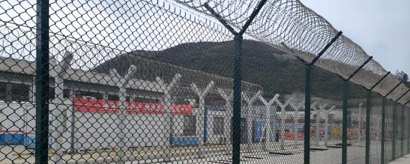
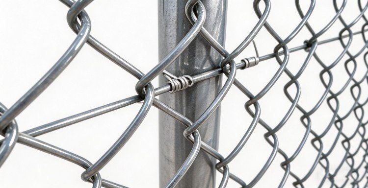 Secure the tension wire to intermediate posts.
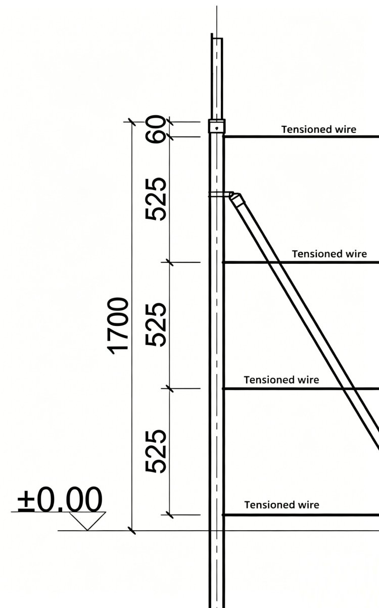
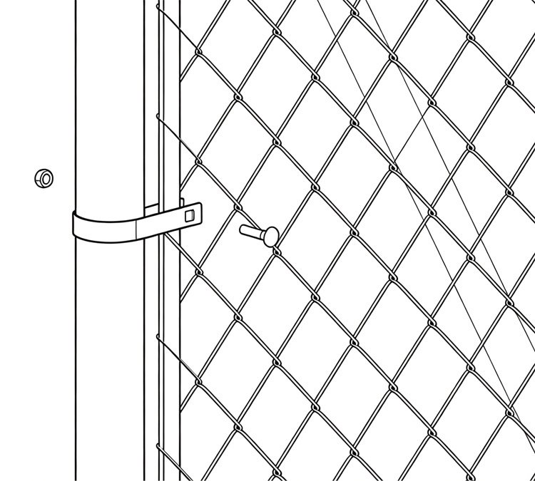
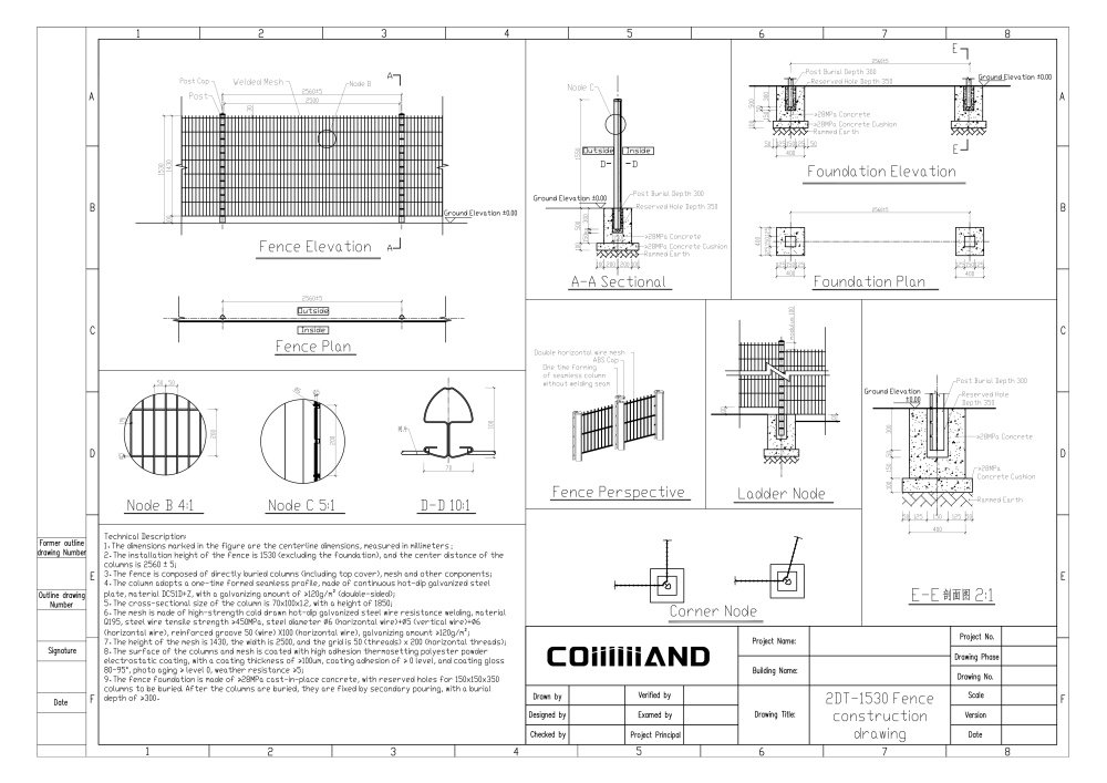
Step 7: Tension and secure the mesh panel
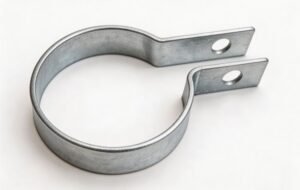
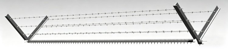
Offset clamp
Five offset clamps are evenly spaced along both the end post and the reinforced post, through which the tensioned flat steel strap tightens the mesh panel.