
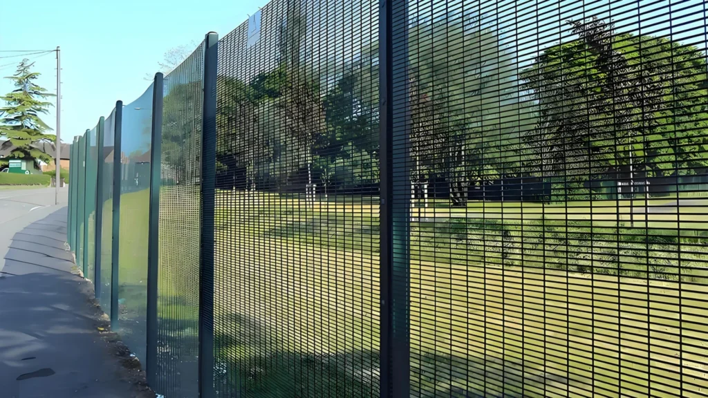
Industrial perimeter fence case study | Welded mesh, Y-arms, razor wire and isolated footing
A high-security fence around a petrochemical or other industrial facility is more than a mesh panel and a post. The supplied Fujian petrochemical-facility calculation considers welded mesh, Y-shaped extension arms, spiral razor-wire coils, connection hardware, steel posts and isolated concrete foundations. Wind actions on these components follow a load path through the connections and posts to the foundations and supporting soil.
This article summarizes the supplied Chinese-code calculation report. Its numerical results are tied to that report’s geometry, material assumptions, wind parameters and foundation assumptions. They should not be treated as a design certificate for another site or as a substitute for calculations under a different jurisdiction’s codes.
1. Define the fence system and calculation unit
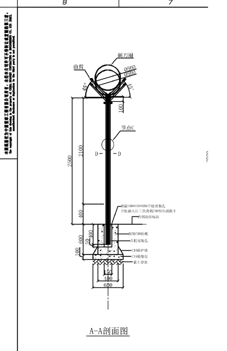
The report checks one standard load unit: a 2,550 mm post spacing, one intermediate post, half a mesh panel on each side, the top Y-arm and razor-wire coils, and an isolated concrete footing.
| Component | Reported configuration |
|---|---|
| Post | 62 × 95 × 1.2 mm multi-cell cold-formed thin-walled section; Q235-grade properties assumed |
| Standard post spacing | 2,550 mm; end and corner spacing reported as 2,525 mm |
| Above-ground post height | 2,500 mm |
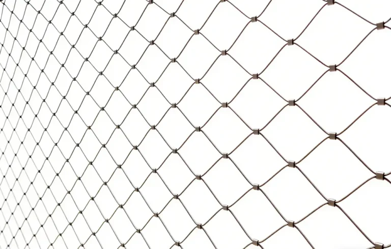
| Welded mesh | Vertical wire Ø5 mm at 50 mm; horizontal wire Ø6 mm at 200 mm |
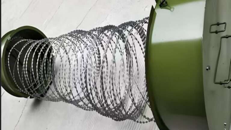
| Top security assembly | 45° Y-arm with two Ø500 mm spiral razor-wire coils |
| Footing | C30 concrete, 600 × 600 × 600 mm; C15 blinding layer 100 mm thick |
| Post embedment | 400 mm, fixed by secondary casting with C30 fine-aggregate concrete |
|
2. Establish the wind basis and component exposure
For the coastal Fujian project, the report adopts a basic wind pressure w0 = 0.80 kN/m², corresponding to a basic wind speed of 35.8 m/s. It uses terrain roughness category B and a height coefficient μz = 0.660 at z = 2.5 m. The report treats wind as the governing action for this low, lightweight fence system.
The report distinguishes the main post structure from cladding components and connections: βz = 1.0 for the main structure, and gust factor βgz = 1.70 for the welded mesh, clips, Y-arms, razor-wire coils and their connections. These are the values and method stated in the source report; a project engineer must confirm the correct coefficients for the actual site and governing code.
The source report uses different solidity assumptions for different parts: the welded mesh has a calculated solidity ratio φ = 0.13 and shape coefficient μs = 0.169; the razor-wire coil is assigned an equivalent solidity ratio of 0.15 and μs = 0.195; the post itself uses a 0.062 m windward width and μs = 1.3.
|
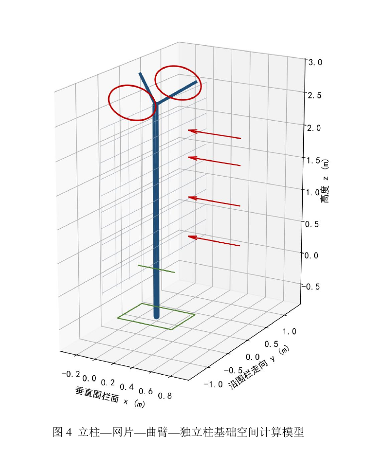
3. Calculate the load transferred to the post
For the 2.55 m standard span, the report calculates the following characteristic wind forces and base-moment contributions. The component heights differ, so their individual moment contributions must be considered.
| Loaded component | Shape coefficient μs | Characteristic force | Load height | Base moment |
|---|---|---|---|---|
| Welded mesh (+0.4 to +2.5 m) | 0.169 | 0.471 kN | 1.53 m | 0.723 kN·m |
| Razor-wire coils (+2.5 to +2.85 m) | 0.195 | 0.109 kN | 2.68 m | 0.292 kN·m |
| Post (0 to +2.85 m) | 1.30 | 0.008 kN | 1.73 m | 0.014 kN·m |
| Total | — | 0.588 kN | — | 1.016 kN·m |
Using the report’s wind load factor of 1.5, the design shear is Vd = 0.882 kN and the design bending moment is Md = 1.524 kN·m. Simply multiplying the total force by post spacing would miss the different load heights and their effects on base moment.
4. Review post strength and lateral deflection
The report models the post as a cantilever fixed at its base and free at the top. It gives a gross section area A = 518.3 mm², strong-axis second moment of area Iv = 511,493 mm⁴ and strong-axis section modulus Wv = 10,768 mm³.
| Check | Reported result | Reported criterion |
|---|---|---|
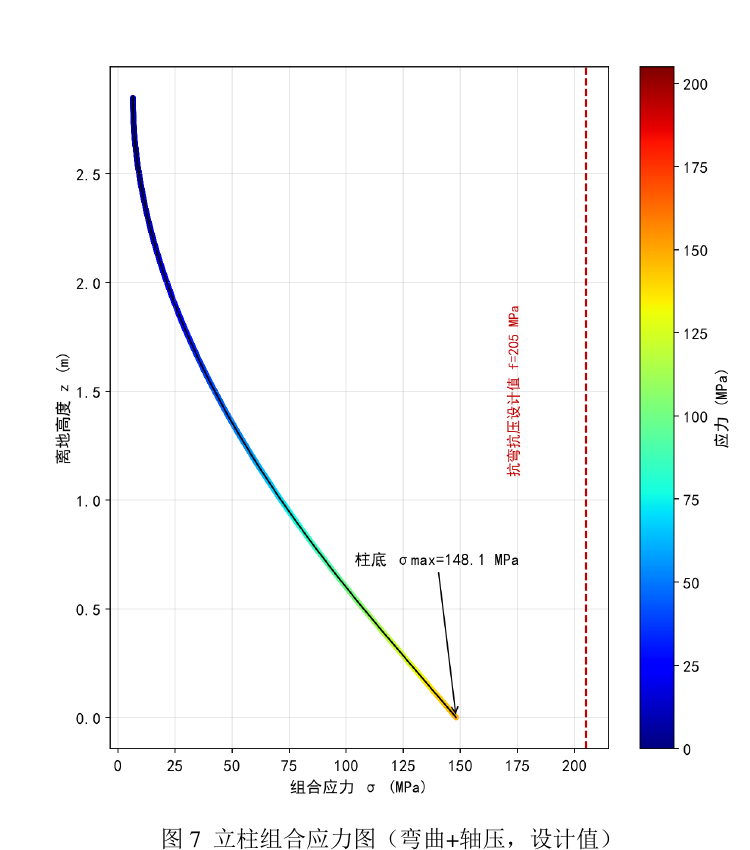
| Combined bending and axial stress | 148.1 MPa | ≤ 205 MPa; stress ratio 0.723 |
| Shear stress | 3.1 MPa | ≤ 120 MPa |
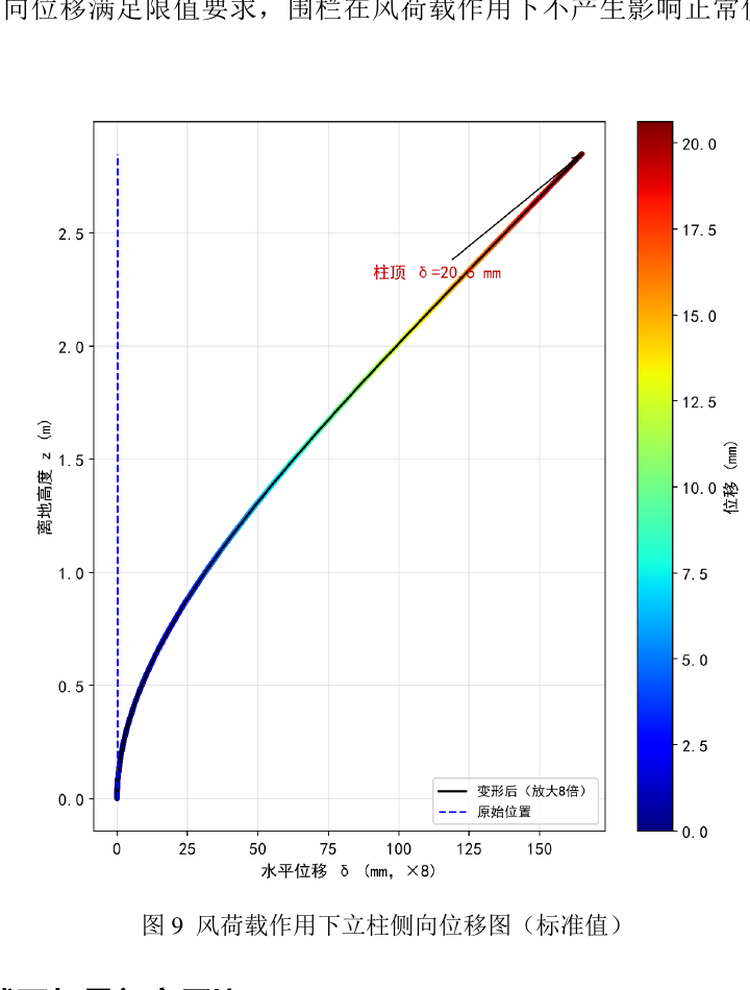
| Top lateral displacement | 20.63 mm | ≤ H/60 = 41.7 mm |
| Section plate width-to-thickness ratio | b/t ≈ 20 | Report treats gross section as effective |
The report concludes that the post meets its stated strength and displacement checks. These conclusions depend on the stated Q235-grade material assumption, section geometry, load model and boundary conditions. If the supplied post’s grade, thickness or section shape differs, the calculation must be reviewed.
|
|
5. Check connections separately
The report applies βgz = 1.70 to the mesh and connection components. It reports a factored mesh force of about 1.20 kN per span; with roughly seven clips per side, the estimated design horizontal force per clip is about 0.086 kN. For the top razor-wire assembly, it reports a gust-adjusted characteristic force of about 0.185 kN and a design force of about 0.28 kN transferred through the Y-arm and clamp.
The report judges the described clips, bolts and clamps adequate under these assumptions. For a real project, confirm the actual connector material, size, quantity, spacing, edge distances and installation method. A generic description cannot replace checking the actual connection detail.
6. Verify the footing and ground assumptions
The report uses a C30 isolated footing measuring 600 × 600 mm in plan and 600 mm high, with a 100 mm C15 blinding layer. The footing base is reported at 0.75 m depth, and the post is embedded 400 mm into a reserved opening and fixed with secondary C30 fine-aggregate concrete.
| Foundation check | Reported result | Report criterion |
|---|---|---|
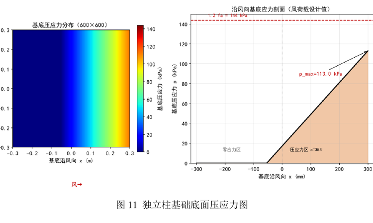
| Maximum soil bearing pressure | 113.0 kPa | ≤ 144 kPa |
| Overturning stability factor | 1.65 | ≥ 1.5 |
| Sliding stability factor | 8.55 | ≥ 1.3 |
A key qualification in the source is that the soil bearing-capacity value fa = 120 kPa is provisional. The report says it must be replaced by the value in the formal geotechnical investigation report. If actual ground conditions are weaker, footing size, embedment or ground improvement may need to be revised by the project designer.
|
Conclusion: Design the full load path
High-security fence wind-load design should follow the load path from the mesh and top security assembly through the connections and posts into the footing and soil. For this Fujian case, the report gives a maximum combined post stress of 148.1 MPa, top displacement of 20.63 mm, maximum foundation bearing pressure of 113.0 kPa, overturning factor 1.65 and sliding factor 8.55. Those results apply only to the report’s inputs, assumptions and stated checks.
About Commandfence
Commandfence supplies metal fencing and perimeter-security products for industrial and infrastructure applications. Share your drawings, project location, fence height, wind criteria and foundation constraints to discuss a configuration aligned with the project specification.
For projects comparing alternative anti-climb mesh configurations, review Commandfence’s 358 fence range. The linked product family should be assessed against the project specification rather than assumed to be equivalent to the configuration calculated here.
Send Commandfence your drawings, required fence height, site wind criteria and foundation constraints for a project-specific product discussion. To start a project discussion, send your drawings and site criteria through Commandfence’s quote form.
Engineering Disclaimer
Before applying this information to an actual project, qualified structural engineers must verify the project loads, materials, fence components, connections, foundations, geotechnical conditions, and compliance with the codes and regulations applicable at the project location. The source report also identifies the soil bearing-capacity value as provisional and requires confirmation against the formal geotechnical investigation report. Do not use this article as the sole basis for engineering approval, construction, or procurement decisions.
This article is provided for general information and reference purposes only. It is not a certified structural design, project-specific engineering approval, or guarantee of performance. The calculations are based on Chinese engineering codes and standards and should not be assumed to demonstrate compliance with the codes or regulations of other countries or jurisdictions.
The calculations and technical information presented in this article are based on the project-specific assumptions, calculation methods, and Chinese engineering codes and standards identified in the source report, including the applicable Chinese national and Fujian provincial standards cited therein. The reported results apply only to the stated project configuration, design inputs, calculation assumptions, and site conditions.






Leave a Reply