
Engineering case study | Wind pressure, tributary load, post strength and lateral deflection
Chain Link Fence Wind Load Calculation: What Engineers Need to Check
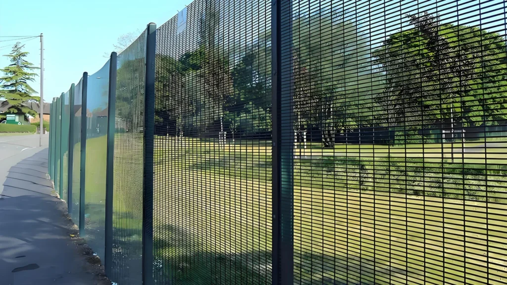
Wind load is an important design consideration for outdoor chain-link fences. Although open mesh allows air to pass through, the wires, posts and connections still experience wind action. Load transferred to each post depends on site wind climate, exposure, mesh solidity, post spacing, steel section properties and support conditions.
This article summarizes the supplied fence-post calculation report prepared using SAP2000. It is a project-specific example, not a universal design method or a substitute for checking the applicable local code.
1. Establish design wind speed and site conditions
The report references ASCE/SEI 7-22 for design loads and ANSI/AISC 360-22 for structural steel design. Its calculation equation uses V = 62.5 m/s (approximately 225 km/h), exposure category C, Kd = 0.85, Kzt = 1.0, Ke = 1.0, a reported risk-category factor Iw = 0.87 and Kz = 0.777. The report calculates qz ≈ 1.37 kN/m².
Wind-speed definition and averaging period, risk category, exposure and coefficients must be checked against the governing standard and actual site. Do not transfer this pressure directly to another project.
2. Account for mesh porosity
The report describes 3 mm wire with 50 × 50 mm openings and an assumed open-area ratio of 88%. It estimates equivalent mesh pressure using:
Using qz = 1.37 kN/m², G = 0.85, Cf = 1.3 and φ = 88%, the reported equivalent mesh pressure is approximately 0.18 kN/m². The porosity method and coefficients must be appropriate for the actual mesh geometry and governing standard.
|
3. Convert mesh pressure to a post line load
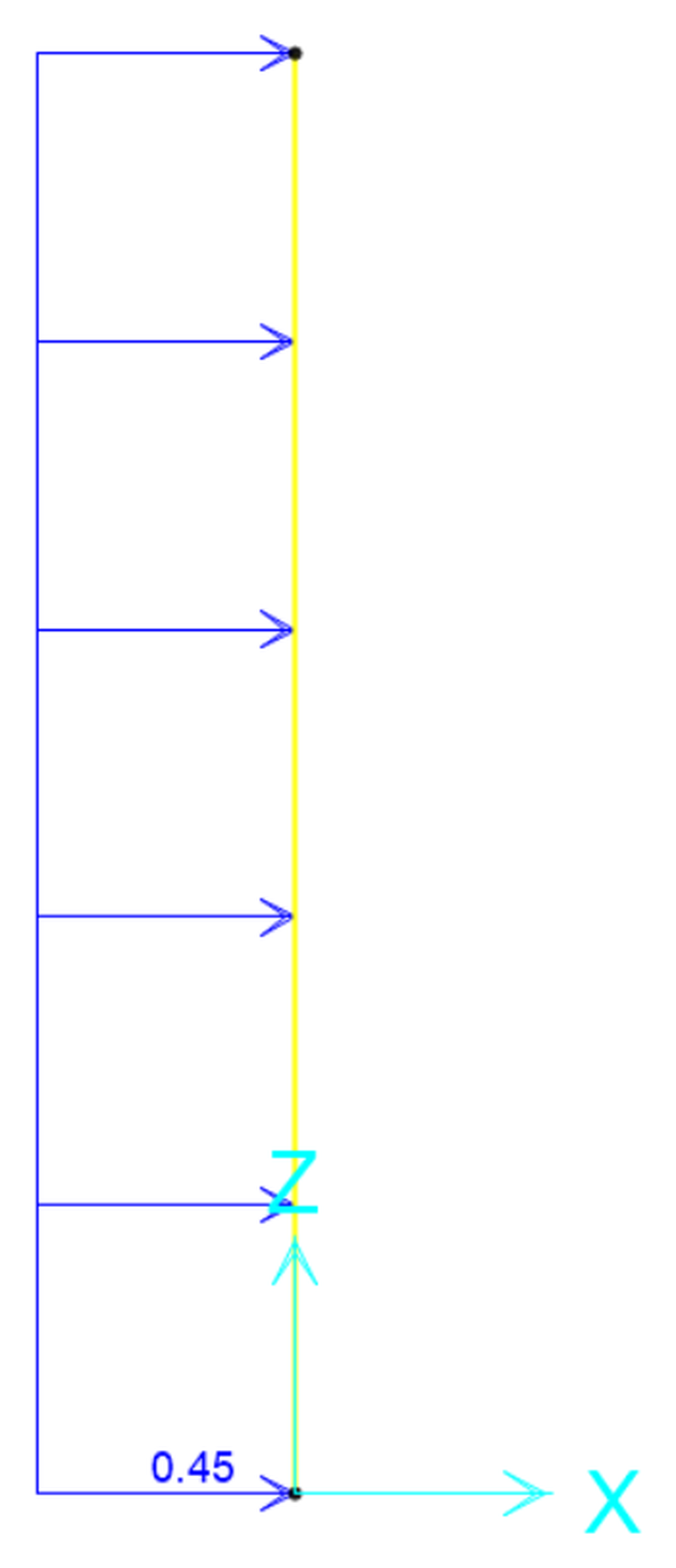
The reported post spacing is 2.5 m. Multiplying equivalent mesh pressure by this tributary width gives:
For the same mesh pressure, wider post spacing generally increases the load tributary to each post. Post spacing, mesh construction and post section should be assessed together.
4. Review the post section and structural response
The model uses a Q355 steel circular hollow-section post, Ø60 × 3.3 mm, reported cross-sectional area 587.82 mm² and member length 2,750 mm.
| Parameter | Value reported in source |
|---|---|
| Post material | Q355 steel |
| Post section | Ø60 × 3.3 mm circular hollow section |
| Cross-sectional area | 587.82 mm² |
| Modelled member length | 2,750 mm |
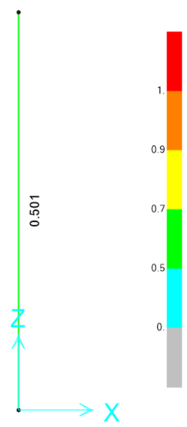
| Reported stress ratio | 0.501 (< 1.0 under the report’s stated criterion) |
The report concludes that the member passes its strength/stability check under the modelled conditions. This result applies only to the reported section, material, loads, boundary conditions and assumptions; it is not a capacity rating for every Ø60 mm post.
|
5. Check lateral deflection
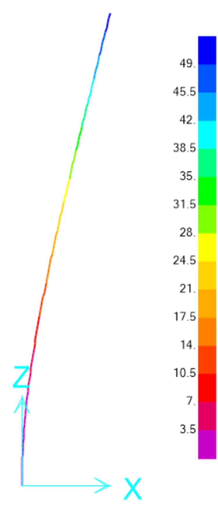
The report gives maximum deformation of 49 mm and adopts a limit of 2,750/50 = 55 mm for the stated 1/1.6W load combination. On that basis, the reported deformation is below the report’s adopted limit. The allowable deflection must be selected from the project specification and governing code; 2750/50 is not a universal fence limit.
|
6. Do not overlook connections and foundations
A post calculation alone does not demonstrate that the complete fence system is adequate. Wind actions pass through mesh attachments into posts and then through post supports into the foundation or ground. Check connection capacity, embedment, foundation stiffness and soil conditions against the actual construction details.
Before using the report for a complete installation, confirm that mesh, clamps, post base or embedment and foundations have suitable design checks, and that the installed configuration matches the model.
Conclusion
This case study reports an equivalent mesh pressure of 0.18 kN/m², a 2.5 m post spacing and a resulting line load of 0.45 kN/m. It also reports a stress ratio of 0.501 and maximum deformation of 49 mm under its stated assumptions. Apply these results only after confirming the inputs, governing code and support conditions for the project.
About Commandfence
Commandfence supplies metal fencing and perimeter-security products for industrial and infrastructure applications. For project enquiries, provide the site location, fence height, mesh specification, post spacing and relevant technical requirements.
For product selection, compare the calculated assumptions with the actual mesh construction, coating specification, post section and installation details in Commandfence’s chain link fence systems.
Share your site location, wind criteria, fence height, mesh specification and post spacing with Commandfence to discuss a project-specific configuration. To start a project discussion, send your drawings and site criteria through Commandfence’s quote form.
Engineering Disclaimer
Before using this information for an actual project, a qualified engineer must independently verify the design wind criteria, loads, materials, structural analysis, connections, supports, and compliance with the codes and regulations applicable to the project location. Do not use this article as the sole basis for engineering approval, construction, or procurement decisions.
This article is provided for general information and reference purposes only. It is not a certified structural design, project-specific engineering approval, or guarantee of performance. Applicable codes, design criteria, and requirements may differ by country, jurisdiction, site exposure, and project specification.
The calculations and technical information presented in this article are based on the project-specific assumptions, analysis methods, and standards cited in the source calculation report, including ASCE/SEI 7-22 and ANSI/AISC 360-22. The reported results apply only to the model, loads, material properties, boundary conditions, and assumptions stated in that report.








Leave a Reply