
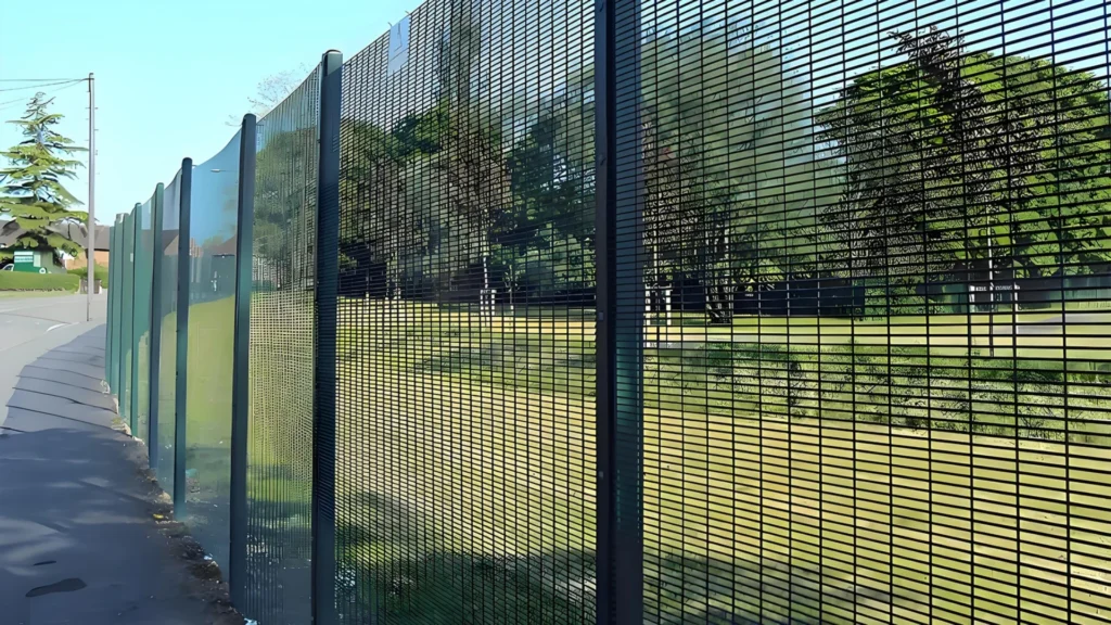
A Security-Zoned Perimeter Strategy for Hydropower Facilities
Hydropower sites commonly extend across natural mountain terrain, riverbanks, service roads, powerhouse areas, general equipment compounds and critical control spaces. These areas differ in public accessibility, operational consequence and required intrusion resistance. This application analysis shows how perimeter requirements can be divided into three security zones and translated into practical technical conditions for alignment, terrain adaptation, structural continuity, foundations, corrosion protection and restricted-area delay.
|
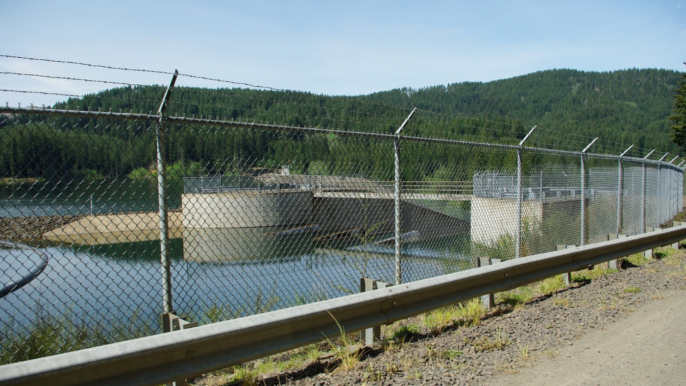
From International Projects to Hydropower Security Zoning
In 2025, Idaho Power carried out perimeter safety improvements at the Oxbow Hydroelectric Plant to restrict public access near the spillway and surge facilities. The scope followed a facility risk assessment, and the physical boundary was positioned around defined hazards and the routes by which people could approach them.
Public-safety guidance from the U.S. Federal Energy Regulatory Commission also emphasizes site-specific assessment based on actual use, public accessibility and the hazards present at each facility. For a large hydropower site with complex terrain, this leads naturally to security zoning: identify the risk and consequence of each area first, then define the perimeter performance required there.
Security-Zoning Logic
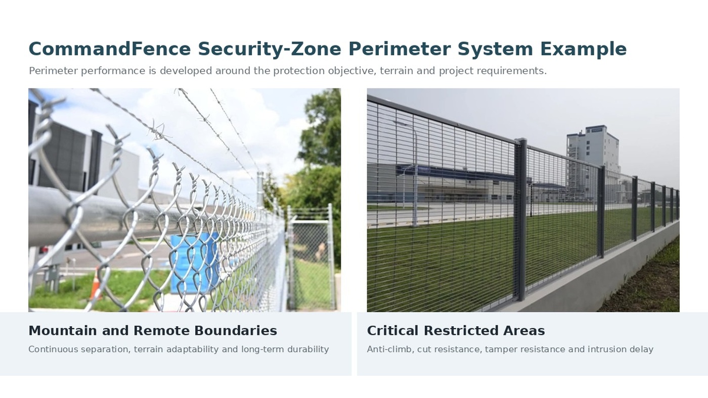
Mountain and remote boundaries primarily reduce accidental entry. Powerhouse perimeters and general operational areas establish a controlled boundary. Control, communications and sensitive equipment areas require greater resistance to climbing, cutting, dismantling and forced entry.
1. Basic Separation Zones: Mountain Boundaries and Remote Slopes
Hydropower perimeters often follow mountain slopes, riverbanks, wooded land or remote maintenance roads. These sections are normally separated from control systems and critical electrical assets. Their primary purpose is to define the managed boundary and reduce accidental entry by visitors, grazing personnel, contractors or other unauthorised people.
The engineering focus is whether the boundary remains continuous, follows changes in grade, controls gaps below the fence line and remains stable under humidity, vegetation growth and surface-water runoff. On long mountain routes, transport access, sectional installation and future local repair should also be considered during detailed engineering.
- Coordinate the alignment with contours, roads and natural obstacles, and avoid bypassable end points at ridgelines, gullies and retaining walls.
- Develop post foundations around the actual soil, rock and drainage conditions. Erosion-prone sections require additional attention to exposed footings and ground settlement.
- Control the clearance between the perimeter and the ground continuously. Local level changes may require stepped sections, raked installation or supplementary closure components.
|
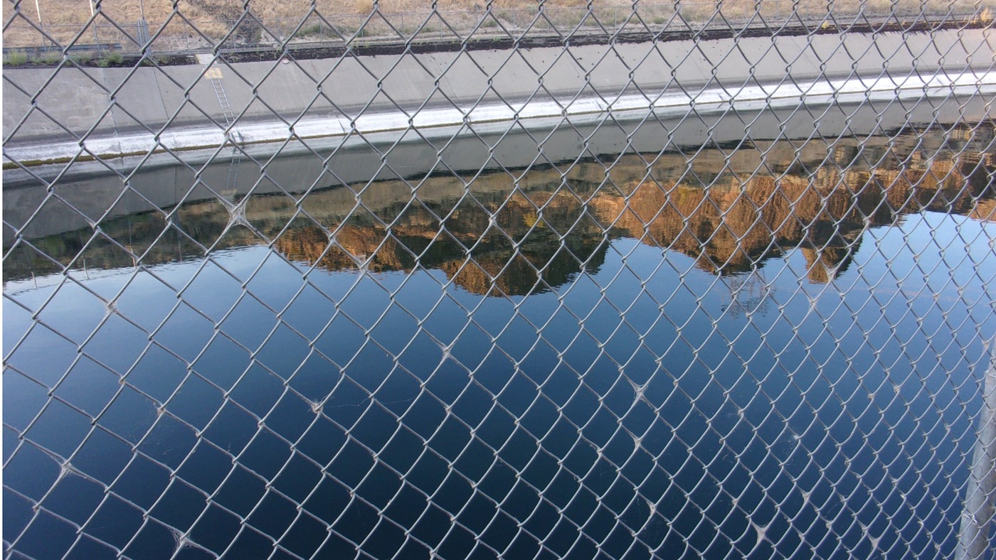
2. Controlled Operational Zones: Powerhouse Perimeters and General Equipment Areas
Around the powerhouse, general equipment areas and routine operational spaces, personnel activity becomes more frequent. The perimeter must limit unauthorised entry while preserving inspection visibility, clear boundary recognition and a stable structural condition.
At this level, the design extends beyond the infill itself. Post spacing, corners, end conditions, foundations, interfaces with buildings or retaining walls and the ability to replace damaged sections all affect long-term performance. Water spray, high humidity, freeze-thaw exposure or saline conditions can also influence the required corrosion-protection system.
- Long straight runs require consistent alignment, post plumb and connection geometry.
- Sections close to roads, loading areas or equipment routes should be reviewed for vehicle and machinery impact.
- Connections to powerhouses, platforms and retaining walls should form a continuous physical boundary without bypassable gaps.
3. Critical Restricted Zones: Control, Communications and Sensitive Equipment Areas
Control, communications, data, protection-relay and other sensitive equipment areas may affect station operation and key assets if approached by unauthorised personnel. In these zones, the perimeter objective moves beyond restricting access and toward increasing attack difficulty and extending the time required to breach the boundary.
The technical requirements should consider climbing, cutting, dismantling and tool-assisted attack. Aperture geometry, material strength, fixing method, post stiffness, end treatment and foundations work together as one system. Increasing height alone does not replace an assessment of the complete perimeter assembly.
- Reduce usable handholds and footholds and increase resistance to cutting with common tools.
- Use fixing and clamping arrangements that reduce the possibility of rapid dismantling from the uncontrolled side.
- Maintain the same protection continuity at corners, end posts and interfaces with permanent structures as along straight sections.
|
4. Transition Details Keep the Security Zones Continuous
Locations where the security level changes are often where weaknesses appear. A flexible line following a mountain boundary may transition to a rigid straight run at a powerhouse platform. As a general operational area approaches a critical restricted zone, height, aperture, fixing and structural requirements may change.
These transition points should be detailed separately. Different posts, infill systems and foundations need defined connection details rather than temporary site overlaps. End conditions should terminate at non-bypassable walls, retaining structures or other permanent barriers, with level changes, pipes, platforms and equipment foundations checked for new climbing or access routes.
Hydropower sites also change over time. Vegetation clearance, erosion, maintenance excavation and newly installed equipment can alter how people move around the site, so zone boundaries and transition details should be included in periodic inspections.
5. Translate Security Zoning into Technical Requirements
Once the security zones are defined, the project team can convert each protection objective into technical requirements that can be manufactured, installed and inspected. The matrix below summarises the principal engineering focus for the three zones.
| Security Zone | Typical Areas | Protection Objective | Key Technical Requirements |
| Basic Separation | Mountain boundaries and remote slopes | Define the boundary and reduce accidental entry | Continuous alignment; terrain adaptation; controlled bottom gaps; corrosion resistance; practical transport, installation and maintenance |
| Controlled Operational | Powerhouse perimeter and general equipment areas | Limit unauthorised access | Structural stability; clear visibility; consistent connections; reinforced corners and ends; long-term environmental durability |
| Critical Restricted | Control, communications and sensitive equipment areas | Increase attack difficulty and delay time | Reduced climbability; cut and tamper resistance; post and foundation stiffness; systemised connections; continuous transition details |
System Integration Note: The boundary should be reviewed as one continuous system. Changes in performance level, structure or foundation type must be resolved through defined transition details rather than temporary site connections.
6. How CommandFence Supports Hydropower Perimeter Projects
CommandFence’s product portfolio covers flexible woven fencing, rigid welded mesh systems and small-aperture high-security fencing across different construction types and performance levels. Once the project security zones have been defined, the required protection objectives can be translated into specific configurations for the mesh or infill, posts, connections, foundation interfaces and corrosion-protection system.
Detailed engineering can begin with the site master plan and risk-zone drawing. Mountain routes, powerhouse boundaries, critical restricted areas and their transition points can be identified and numbered separately. Materials and structural parameters can then be selected around the terrain, exposure environment, design life and project specification, followed by elevations, corner details, wall interfaces and foundation drawings.
During manufacturing and delivery, CommandFence can label and package the infill, posts and fittings by zone and installation sequence. This helps the site team distinguish materials intended for different protection levels and reduces mixing, temporary modification and installation errors.
Recommended Information for Detailed Engineering
- Site master plan, perimeter alignment and topographical information
- Identification of mountain boundaries, operational areas and critical restricted zones
- Required perimeter height, foundation conditions, exposure environment and design life
- Project technical specifications, structural loads and acceptance requirements
- Interfaces with buildings, retaining walls, roads and existing infrastructure
7. Conclusion
A hydropower perimeter may cross natural mountain terrain, operational spaces and critical technical areas. Public accessibility, asset importance and the consequence of entry vary across these zones, so the required perimeter performance changes with them.
Mountain boundaries focus on continuous separation and terrain adaptation. General operational areas require stability, visibility and maintainability. Critical restricted areas require greater resistance to climbing, cutting, dismantling and forced entry. Transition points, end conditions and foundations determine whether these objectives remain continuous across the complete site.
CommandFence can support hydropower projects with security-zone configuration, detailed drawings, custom manufacturing and zone-based delivery planning.
Planning a Hydropower Perimeter Project
When a project has a site master plan, a perimeter alignment or an initial security-zone concept, CommandFence can help develop the technical requirements, interfaces, detailed drawings, custom production and installation preparation step by step.
Engineering Note: The final perimeter structure, materials, dimensions, foundations and corrosion-protection system should be confirmed against the project risk assessment, technical specifications, terrain conditions and approved drawings.






Leave a Reply